|
PARTS LIST
IC1 - - - - - - - - - - - - - - - - - - - - - - - - - -LM7808
Q1 - - - - - - - - - - - - - - - - - - - - - - - - - - C4242
D1,D2,D3,D4 - - - - - - - - - - - - - - - - - - - -1N5400
Heatsink - - - - - - - - - - - - - - - - - - - - - - 5cm x
5cm aluminum
No 18AWG insulated hook up wire - - - - - -1.5 meters
Note: Except for IC1 (LM7808), all parts used in the fabrication
of a prototype circuit were taken from a junked computer power
supply.
CONSTRUCTION
This circuit is very easy and simple to construct for there
is no need to design and fabricate printed circuit board (PCB).
Just follow the procedure below in order to avoid any mistake.
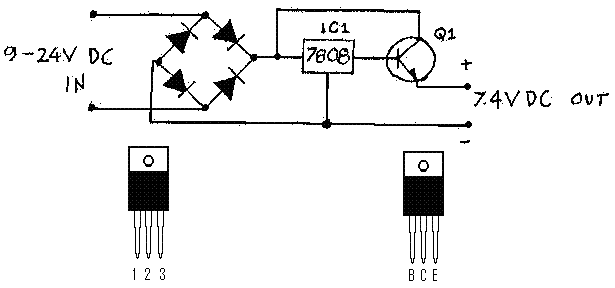
1. Arrange and solder the four diodes as shown in the schematic
diagram. Identify its terminals carefully.
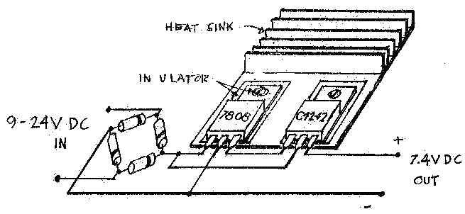
2. Place and screw IC1 at the left portion of the PCB. Don't
forget to insulate it from the heatsink.
3. Place and screw transistor Q1 at the right portion of the
PCB. Like IC1, it should be insulated from the heatsink.
4. Following the schematic diagram, make necessary connections
among components. (See pin designation of IC1 and Q1 below
Figure 1)
5. Recheck every connection made and proceed with testing
CHECKING AND TROUBLESHOOTING
Connect this circuit to any DC voltage source with voltage
ranging from 9V to 24V. Measure the voltage at the input lead
of the IC1. It should be equal to the source voltage. If not,
recheck the connections of four diodes. Measure the voltage
at the output lead of the IC1. It should measure 8V, if not,
IC1 is defective. Replace it and repeat the voltage test until
you get 8V. Measure the voltage at the output of the circuit.
It should read approximately 7.4V. This voltage reading is
approximately equal to the voltage of a full-charged battery
pack. You can now connect temporarily your HH radio with the
use of connecting wires to the circuit. Carefully observe
and recheck its output polarity before powering on your HH
radio. While monitoring the output voltage with your multi-tester
set at 10 DCV, try to transmit on low power first. The voltage
drop should be unnoticeable. If so, you can now transmit on
high-power. The voltage drop should only be 0.2V or less.
If you obtain this value, then both IC1 and transistor Q1
is functioning properly and you can now permanently layout
all components inside an emptied battery pack. If the voltage
reading drop greater than 0.2V , try to replace Q1, you should
obtain these required voltage readings when all components
are good. It is very seldom that IC1 will fail because of
its inherent characteristics and protection.
Figure 1

1 - in
2 - ground
3 - out
Figure 2

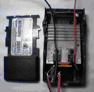
Figure 3
(Actual photo of the circuit inside emptied battery pack
of GP68)

|